
A collaboration diagram in UML (Unified Modeling Language) is a crucial tool for visualizing interactions between objects in a system. For order processing systems, this diagram helps illustrate how various components collaborate to process customer orders efficiently. Let's explore the essential elements of a collaboration diagram and how it can be applied to optimize order processing workflows.
What is a Collaboration Diagram?
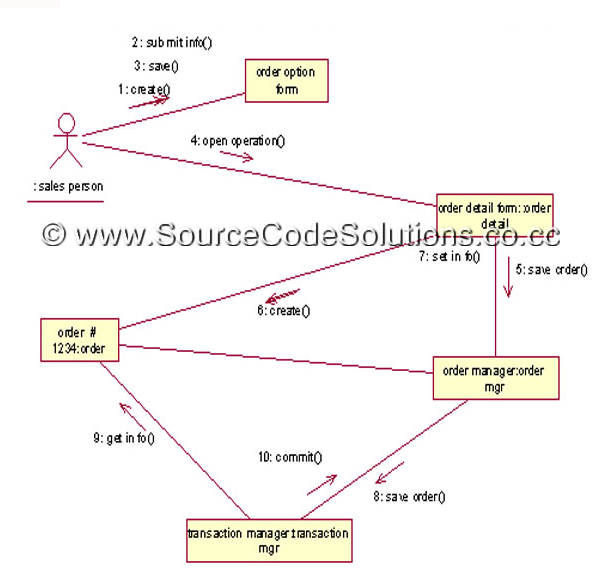
A collaboration diagram represents how objects within a system interact with each other, focusing on their communication and the sequence of messages. Unlike sequence diagrams, which emphasize the time order of events, collaboration diagrams focus on the relationships and interactions between objects.
Why Use a Collaboration Diagram for Order Processing?
In an order processing system, a collaboration diagram helps identify the flow of operations between the customer, order management, inventory, payment system, and other related components. By creating such a diagram, you can spot inefficiencies, streamline the process, and ensure all systems communicate correctly.
Key Components of the Diagram:
- Actors: Entities such as customers, systems, and administrators that initiate or receive actions.
- Objects: Key system components like Order Management, Inventory, Payment Gateway, etc.
- Messages: Interactions between objects, typically displayed as numbered arrows to indicate the order of actions.

Step-by-Step Walkthrough of the Order Processing Scenario:
- Customer Places Order: The customer interacts with the order management system, which initiates the order process.
- Inventory Check: The system checks if the requested items are available in the inventory.
- Payment Processing: If the items are available, the order is processed, and the payment system handles the transaction.
- Order Confirmation: The system sends a confirmation to the customer and updates the inventory accordingly.
Best Practices for Creating Collaboration Diagrams:
- Keep the diagram simple and focused on key interactions.
- Use appropriate labels for each object and message to avoid confusion.
- Ensure the diagram is aligned with the overall system architecture.